Monocrystalline Silicon Pressure Transducer Working Principle
Monocrystalline silicon pressure transducers are one of the most common pressure transducers in industrial production. Monocrystalline silicon is a good semiconducting material. The monocrystalline silicon pressure transducer is fabricated using a high performance piezoresistive pressure core. This paper describes the working principle of monocrystalline silicon pressure transducer and the realization process of high stability and high accuracy performance. The key points include the selection of monocrystalline silicon chips, the stress-free packaging of monocrystalline silicon wafers, the elimination of backlash errors, the reduction of static pressure effects, and the amplification of the range ratio. In these ways, enhance the full performance, accuracy level and reliability of the pressure transducer. As a precision measurement instrument, monocrystalline silicon pressure transducer is very common in the field of automation, which is of great significance.

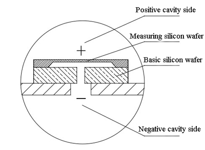
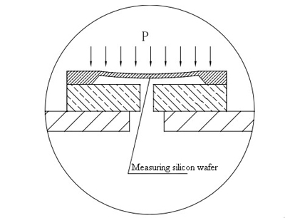
As shown in the figure below. Under the action of the pressure difference between the positive chamber and the negative chamber, there are deformation and bending to the measuring silicon diaphragm (ie, the elastic member). When the pressure difference P is smaller than the limit σp of the allowable stress ratio of the silicon diaphragm, the bending can be completely reset. When the pressure difference P is greater than the limit σp of the allowable stress ratio of the silicon diaphragm, it will reach the yielding phase of the material, even to the strengthening phase. At this time, the silicon diaphragm cannot be recovered to the original position after the pressure difference is removed, resulting in an irreversible measurement deviation. When the pressure difference P reaches or exceeds the highest stress σb that the silicon diaphragm can withstand, the silicon diaphragm will be broken. It will directly damage the pressure transducer. Therefore, by preventing or weakening the external overload pressure difference P directly transmitted to the measuring silicon diaphragm, the measurement accuracy and life of the pressure transducer can be effectively protected. It leads to the problem of overload protection design for single monocrystalline chips.

For example, a capacitive differential pressure transducer is combined with a throttling device to form a differential pressure flow meter. Under the static pressure of 32MPa, the full-scale static pressure error is ≤±2% FS. Although its zero error can be eliminated by zeroing, the full-scale output error cannot be avoided. Therefore, the static pressure error will directly affect the flow measurement, and the impact is large. Under this application condition, the static pressure performance of the differential pressure transducer is particularly important.
If the static pressure error is compensated, or its own static pressure error is extremely small, the measurement accuracy of the pressure transducer will be greatly improved. The monocrystalline silicon differential pressure transducer uses a unique monocrystalline silicon chip packaging process. After encapsulation, the inner and outer chambers are pressure balanced. When a working static pressure is applied to the positive and negative chambers of the measuring silicon wafer, the working static pressure is loaded onto the measuring silicon wafer in a balanced manner. The positive cavity silicone oil outside the silicon wafer and the negative cavity silicone oil inside the silicon wafer transmit this working static pressure. At the same time, mutual cancellation is achieved, so that the bending and deformation of the measuring silicon wafer under the action of the working static pressure is extremely small. The treatment greatly enhances the static pressure effect performance of the differential pressure transducer.

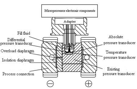
In applications where the differential pressure transducer is used, the differential pressure signal amount is too small. Therefore, the differential pressure transducer is very sensitive to the effects of static pressure. The unique package design and process described above still does not completely eliminate or attenuate the effects of static pressure. Therefore, for this problem, in the differential pressure measurement application, an absolute pressure transducer capable of measuring the static pressure can be integrated inside the measurement system. The absolute pressure transducer can feed the measured working static pressure signal to the microprocessor in the system in real time. The microprocessor automatically corrects the differential pressure output signal by using the working static pressure coordinate axis. In this way, the purpose of static pressure compensation is achieved. Through the unique packaging process and the installation of absolute pressure transducers, the static pressure performance of the differential pressure transducer is greatly improved. Thereby, the measurement accuracy and high stability of the differential pressure transducer can be ensured.
- Working principle of the monocrystalline silicon pressure transducer
As shown in the figure below. Under the action of the pressure difference between the positive chamber and the negative chamber, there are deformation and bending to the measuring silicon diaphragm (ie, the elastic member). When the pressure difference P is smaller than the limit σp of the allowable stress ratio of the silicon diaphragm, the bending can be completely reset. When the pressure difference P is greater than the limit σp of the allowable stress ratio of the silicon diaphragm, it will reach the yielding phase of the material, even to the strengthening phase. At this time, the silicon diaphragm cannot be recovered to the original position after the pressure difference is removed, resulting in an irreversible measurement deviation. When the pressure difference P reaches or exceeds the highest stress σb that the silicon diaphragm can withstand, the silicon diaphragm will be broken. It will directly damage the pressure transducer. Therefore, by preventing or weakening the external overload pressure difference P directly transmitted to the measuring silicon diaphragm, the measurement accuracy and life of the pressure transducer can be effectively protected. It leads to the problem of overload protection design for single monocrystalline chips.
- Pressure overload protection for the monocrystalline silicon pressure transducer
- Superior range ratio adjustable performance of the monocrystalline silicon pressure transducer
- Superior pressure hysteresis performance of the monocrystalline silicon pressure transducer
- Unique static pressure characteristics of the monocrystalline silicon pressure transducer
For example, a capacitive differential pressure transducer is combined with a throttling device to form a differential pressure flow meter. Under the static pressure of 32MPa, the full-scale static pressure error is ≤±2% FS. Although its zero error can be eliminated by zeroing, the full-scale output error cannot be avoided. Therefore, the static pressure error will directly affect the flow measurement, and the impact is large. Under this application condition, the static pressure performance of the differential pressure transducer is particularly important.
If the static pressure error is compensated, or its own static pressure error is extremely small, the measurement accuracy of the pressure transducer will be greatly improved. The monocrystalline silicon differential pressure transducer uses a unique monocrystalline silicon chip packaging process. After encapsulation, the inner and outer chambers are pressure balanced. When a working static pressure is applied to the positive and negative chambers of the measuring silicon wafer, the working static pressure is loaded onto the measuring silicon wafer in a balanced manner. The positive cavity silicone oil outside the silicon wafer and the negative cavity silicone oil inside the silicon wafer transmit this working static pressure. At the same time, mutual cancellation is achieved, so that the bending and deformation of the measuring silicon wafer under the action of the working static pressure is extremely small. The treatment greatly enhances the static pressure effect performance of the differential pressure transducer.

In applications where the differential pressure transducer is used, the differential pressure signal amount is too small. Therefore, the differential pressure transducer is very sensitive to the effects of static pressure. The unique package design and process described above still does not completely eliminate or attenuate the effects of static pressure. Therefore, for this problem, in the differential pressure measurement application, an absolute pressure transducer capable of measuring the static pressure can be integrated inside the measurement system. The absolute pressure transducer can feed the measured working static pressure signal to the microprocessor in the system in real time. The microprocessor automatically corrects the differential pressure output signal by using the working static pressure coordinate axis. In this way, the purpose of static pressure compensation is achieved. Through the unique packaging process and the installation of absolute pressure transducers, the static pressure performance of the differential pressure transducer is greatly improved. Thereby, the measurement accuracy and high stability of the differential pressure transducer can be ensured.

