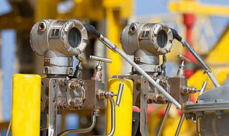
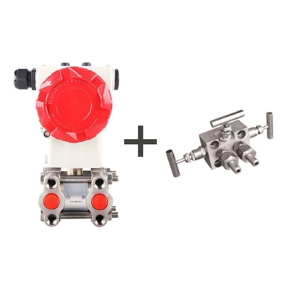
Differential Pressure Sensor in Use with Three Valves Manifold
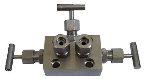
The three valves manifold is a matching tool that must be used in the differential pressure sensor installation and demolition. It consists of a valve body, two shut-off valves and a balancing valve. In the middle is a balancing valve and two shut-off valve at both ends.

The main function of the three valves manifold is to use the balance valve when installing and removing the differential pressure sensor. Otherwise, the range of differential pressure sensor is generally small. If the overload capability of the sensor is not strong, it is easily damaged.
Giving a simple example: assume that the differential pressure is 60KPa and the pipe pressure is 1MPa. If there is no balancing valve, whether taking the pressure of the positive pressure chamber or the negative pressure chamber first, it will immediately cause the differential pressure on both sides to exceed the set value. Because the pressure taken first will directly communicate with the atmosphere, equivalent to 0.1MPa, this operation is fatal.


Static balancing valve is also called balancing valve, manual balancing valve and double position regulating valve, etc. It changes the flow resistance of the valve to adjust the flow by changing the clearance (opening degree) between the valve core and the valve seat and adjusting the Kv (valve flow capacity) of the valve. Its action object is the system resistance. It can eliminate the phenomenon that unbalanced resistance in the system, so that the new water quantity can get a balanced distribution according to the proportion calculated by the design, and each branch can be proportional increase or decrease at the same time.
Dynamic balancing valves are divided into dynamic flow balancing valves and dynamic differential pressure balancing valves.
The shut-off valves can be divided into three types according to the connection method: flange connection, threaded connection and welded connection. For a self-sealing shut-off valve, the medium flow direction is from above the valve flap into the valve cavity. At this time, under the action of the medium pressure, the force when closing the valve is small and the force when opening the valve is large, so the diameter of the valve stem can be correspondingly reduced. At the same time, under the action of the medium, this type of valve structure is relatively strict.

- Functions of the three valves manifold
The main function of the three valves manifold is to use the balance valve when installing and removing the differential pressure sensor. Otherwise, the range of differential pressure sensor is generally small. If the overload capability of the sensor is not strong, it is easily damaged.
Giving a simple example: assume that the differential pressure is 60KPa and the pipe pressure is 1MPa. If there is no balancing valve, whether taking the pressure of the positive pressure chamber or the negative pressure chamber first, it will immediately cause the differential pressure on both sides to exceed the set value. Because the pressure taken first will directly communicate with the atmosphere, equivalent to 0.1MPa, this operation is fatal.
- Operation sequence when the differential pressure sensor is put into operation
- Open the two drain valves on the differential pressure sensor, then open the balancing valve, and then slowly open the two shut-off valves to remove air or dirt from the pressure guiding tube.
- Close the two drain valves, close the balancing valve, and the sensor is ready for operation.
- The differential pressure sensor can be zero-checked by opening the balancing valve and closing the two shut-off valves.

- Correct use of the three valves manifold
- When starting the meter, first open the middle balance valve.
- Open the left and right inlet valves at the same time.
- Close the balance valve in the middle.
- The operation sequence when turning off the meter is the reverse of the above.
- When the pipe is added with the medium from the initial state (empty), the pressure on both sides of the pressure sensor suddenly changes, and the pressure difference increases. To avoid this, first close the valves A and B on both sides of the sensor and open the bypass valve C.
- After the pipe is filled with medium and approaching smooth and balanced, gradually open A and B and apply pressure evenly on both sides of the sensor.
- Then close valve C and the pressure sensor starts working normally.
- The operation sequence when turning off the meter is the reverse of the above.
- Operations when the three valves manifold is put into use
- Check if the pipeline is connected properly and the drain outlet is well sealed to prevent medium leakage.
- Open the balancing valve so that the high and low pressure sides are simultaneously pressurized.
- Open the high pressure shut-off valve to receive the process piping pressure.
- Close the balancing valve so that both sides are under positive pressure.
- Open the low pressure shut-off valve and enter the measurement state.
- Operations when closing the three valves manifold
- Close the low pressure shut-off valve.
- Open the balancing valve.
- Close the high and low pressure shut-off valves.
- Close the balancing valve.

- Definition of the balancing valve
Static balancing valve is also called balancing valve, manual balancing valve and double position regulating valve, etc. It changes the flow resistance of the valve to adjust the flow by changing the clearance (opening degree) between the valve core and the valve seat and adjusting the Kv (valve flow capacity) of the valve. Its action object is the system resistance. It can eliminate the phenomenon that unbalanced resistance in the system, so that the new water quantity can get a balanced distribution according to the proportion calculated by the design, and each branch can be proportional increase or decrease at the same time.
Dynamic balancing valves are divided into dynamic flow balancing valves and dynamic differential pressure balancing valves.
- Dynamic flow balancing valve is also called flow limiting valve, constant flow valve, automatic balancing valve, etc. It automatically changes the drag coefficient according to changes in system operating conditions (pressure difference). It can effectively control the flow passing through and maintain it be a constant value within a certain pressure difference range. When the pressure difference between the front and the back of the valve increases, the flow can not be increased by the automatic closing action from the valve. Conversely, when the pressure difference is reduced, the valve automatically opens and the flow remains constant. However, when the pressure difference is less than or greater than the normal operating range of the valve, since it does not provide additional pressure after all, the flow is still lower or higher than the set value when the valve is fully open or fully closed. Usually dynamic flow balancing valves are used in constant flow systems.
- Dynamic differential pressure balancing valve is also called self-operated differential pressure control valve, differential pressure controller, differential pressure balancing valve, etc. It uses the pressure difference to adjust the valve opening degree, and uses the pressure drop of the valve core to compensate for the change of the pipeline resistance, so that the meter can keep the pressure difference basically unchanged when the working condition changes. Its principle is effectively controlling the constant pressure difference for the system within a certain flow range. When the pressure difference in the system increases, it can ensure the system pressure difference increases by the automatic closing action of the valve. Conversely, when the differential pressure is reduced, the valve automatically opens and the differential pressure remains constant.
- Definition of the shut-off valve
The shut-off valves can be divided into three types according to the connection method: flange connection, threaded connection and welded connection. For a self-sealing shut-off valve, the medium flow direction is from above the valve flap into the valve cavity. At this time, under the action of the medium pressure, the force when closing the valve is small and the force when opening the valve is large, so the diameter of the valve stem can be correspondingly reduced. At the same time, under the action of the medium, this type of valve structure is relatively strict.

